Forward Reverse Motor Control Diagram With Timer
The motor with run on power up in one direction (relay off) and when the control signal is applied it will reverse direction (relay on). The overload contacts are connected to l1 on one side and to the plc’s input module on the other (input 003).
Reverse Forward Motor Control Circuit Diagram For 3 Phase
Forward reverse motor control diagram with timer zener diode :

Forward reverse motor control diagram with timer. Controlling 3 phase induction motor using vfd and plc. Latching rung to operate the system through master start and stop pb. 3 phase ac motor control wiring diagram pdf typical circuit of direct the for dc adopt auto star delta and forward reverse switching single circuits applied.
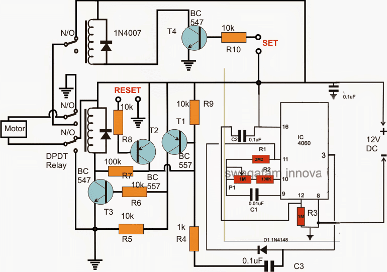
Each part ought to be set and connected with different parts in. When using a dpdt relay you need to reverse the connections to nc2 and no2 shown in the diagrams above. The 555 timer integrated circuit connects to a second relay that disrupts power to the track and causes the trolley to stop.
Switch on the main and sub feeder isolating circuit breakers (q1, q2). Forward reverse motor control diagram with timer pdf madcomics. Please bear in mind the higher current drawn when the motor is reversed without first being stopped and ensure that it.
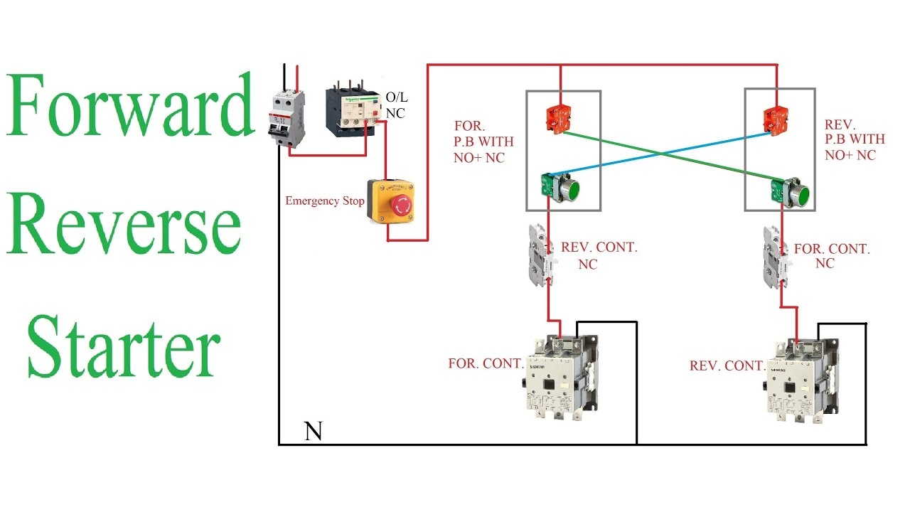
Now in the below diagrams three phase motor will rotate in two directions viz forward and reverse. The power circuit and schematic wiring diagram shows that l1 and l3 have been changed for. This may not be perfect but should work.
Both motor starters and control relays have contactsno post that change their state as soon as the coil is energized. The dc motor is connected to the supply through dpdt ( double pole double through ) switch, by changing the. Use the start and stop pushbuttons for motor operation.
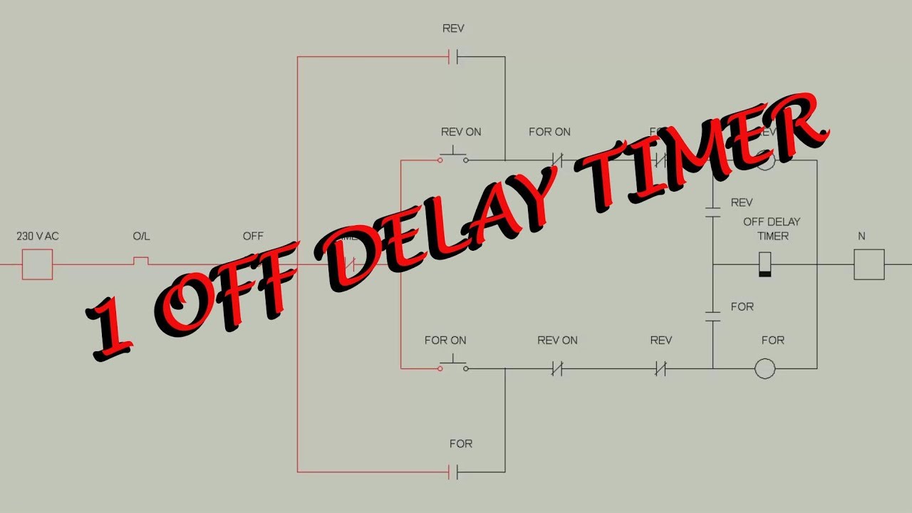
An electric drill forward and reverse rotation automatic switching apparatus includes: If a circuit requires some sort of delay in timing action, perhaps for sequence control or safety purposes, then timing relays can be used. In this website we already published about speed control of dc motor with timer ic, here this circuit constructed for the basic motive to meet the forward / reverse operation of dc motor with speed control.
Three phase motor connection star delta y d reverse forward with timer power control diagram electrical technology electrical circuit diagram circuit diagram electrical diagram. Motor control circuit diagram forward reverse with timer. This is done to avoid dead short circuit in case both the contactors closing simultaneously.
Three phase motor connection stardelta y reverse and forward with timer power control diagram as we have already shared the starting method of three phase motor by star delta starter with timer circuit power and control circuits. But we have controlled the direction of rotation of this three phase motor by a timer circuit. So far all the circuits we have been looking at have all used instantaneous contacts.
, add a second normally open pushbutton, and add a holding contact branch for the second coil. Stop the motor and then press the reverse direction pushbutton to change the rotation of the motor. In the forward reverse timer diagram all main and control wiring shown.
Press the forward direction pushbutton. Connect the circuits as shown in the diagram. Auto forward & auto reverse motor control circuit.
Forward re verse control developing a wiring diagram and reversing single phase split motors electric equipment. Motor forward and reverse control. A single stop button is sufficient to disable the motor in both directions.
A brushless esc is a very complex piece of kit. List of inputs and outputs. To run the motor of above 05 hp rating circuit has to.
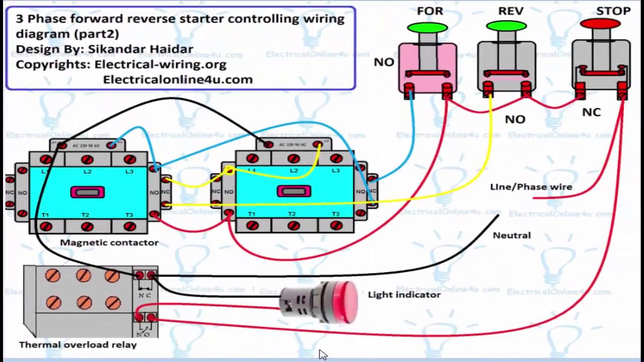
In this wiring diagram, both the forward and reverse coils have their returns connected to l2 and not to the overload contacts. In the event of an overload, both motor starter output coils will be dropped from. Welcome of all visitor of this site, in this video we can see you that how the electrical circuit of 3 phase motor is controlled and we can see you full practical video of this circuit and we are explain this circuit with diagram.
A single stop button is sufficient to disable the motor in both directions. O/l = over load relay no = normally open nc = normally close for = forward rev = reverse t = timer. When designing the control schematic for forward / reverse circuits, we start with the standard.
A forward reverse starter with timer for 3 phase motor diagram in the forward reverse timer diagram all main and cont electrical circuit diagram timer diagram The way to control 2 brushless motors is to use 2 esc's in parallel via a 'y' lead to the receiver. I would not recommend that it is used to control 2 motors because it does have inbuilt sensors to monitor what a specific motor is doing.
Reverse forward star delta connection || star delta forward reverse motor connection || diagramhello am irfan from iie (irfan industrial electronics)aj me ap. When the workpiece is near limit switch1, it will enable forward motor, for latching forward motor is connected in parallel with limit switch 1. 0 75hp 110 220 single phase motor circuit diagram electrical.
Image result for forward reverse 3 phase motor electrical projects electrical circuit diagram motor. Plc implementation of forward reverse motor circuit with interlocking.
Off Delay Timer Wiring Diagram Wiring Diagram
Forward Reverse Star Delta Circuit Diagram Wiring Diagram

Diagram Star Delta Control Wiring

A how to guide for the Control Circuit of a Forward

[Download 42+] Star Delta Forward Reverse Motor Control
Forward Reverse 3 Phase AC Motor Control Wiring Diagram

Dc Motor Control Circuit Diagram Forward Reverse Irish
MOTOR CIRCUITS Auto Forward & Auto Reverse "motor

Forward Reverse Motor Control Diagram For 3 Phase Motor
[Download 35+] Diagram Forward Reverse Motor Control With
Electrical Engineering World Power & Control Circuit for

Forward Reverse Starter With Timer 3 Phase Motor Wiring

Three Phase Motor Connection Star/Delta (YΔ) Reverse

forward reverse starter working principle * reverse
Forward Reverse Motor Control Diagram With Timer Pdf

Control Star Delta Forward Reverse Wiring Diagram Pdf

[VK_0534] Control Forward And Reverse For A Threephase

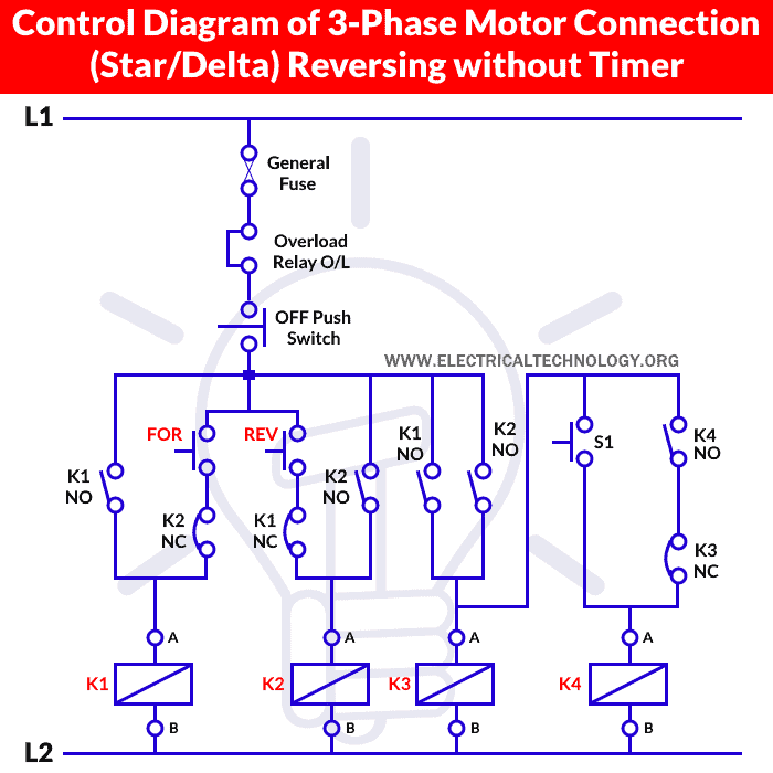
Three Phase Motor Star/Delta Reverse & Forward without Timer
Rangkaian Reverse Forward DIKBUD
